1. Minimum product knowledge required to do estimation and offer submission.
2. Availability of a variety of Feeder Configurations as samples to choose from, resulting in time saving Updated Price List available at site , which can be downloaded
3. Single point modification of, say Discount, at any stage of the offer for a particular Make’s family (e.g. ACBs) Component costing,
4. Feeder / Module costing,
5. Panel costing
5. Project costing
5. Costing of Electrical material & Labor is maintained component-wise ,
5. Tender purpose General Arrangement Drawing generated automatically
6. Technical validations ensure that wrong data selections are limited

Benefits of Engineering solution
1. Engineering process becomes system dependent and not totally person dependent.
2. To a greater extent, the quality is controlled by system.
3. Drawing quality improvement due to negligible drafting errors, ease of drawing reading, standardized formats.
4. Creation of knowledge bank as the database gets built.
5. Automation of time consuming manual activities.
6. Database of frequently used switchgear components and their symbols gets created
7. Built-in intelligence helps avoid illogical errors.
8. Apart from the above intangible benefits, there are tangible benefits in the form of lead time reduction, resulting in reduction in amendments due to engineering errors
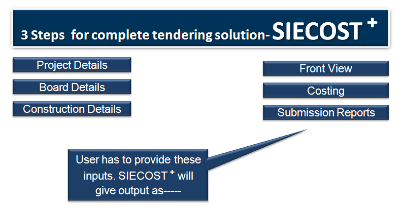
OUTPUT from Engineering solution
1. Record of Drawings – Automatic
2. Technical Details – Semi-automatic
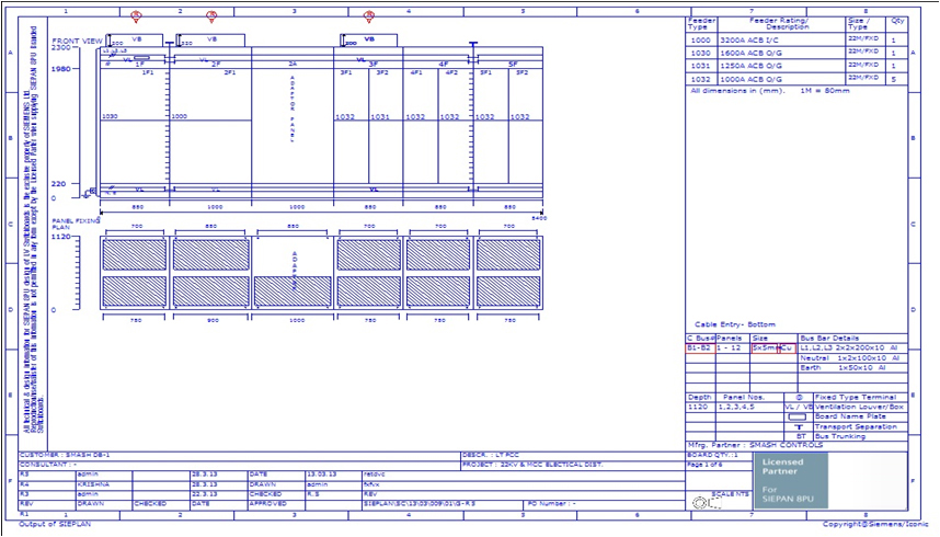
3. Front View along with Panel Fixing Plan – Automatic
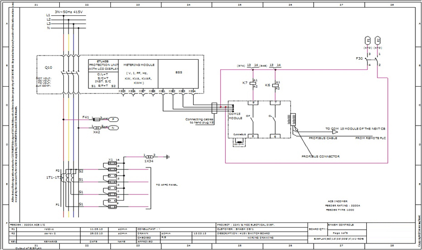
4. Wiring / Scheme Drawings with Terminal Diagram – Semi-automatic
5. Single line diagram – Automatic
6. Bill of materials and Master Bill of materials – Automatic
7. Door layout drawings - Semi-automatic
8. Name plate list – Semi-automatic
9. List of changes in BOM (due to amendment in drawings) - Automatic
Front view feature list
Engineering solution has many features which makes it easy to generate output with accuracy in less time. The best part is that without making a single line complete Front view is generated in all respect.
1. Based on the requirement, user can easily change the board category as Compartmentalized or non- Compartmentalized.
2. It is possible to make board as single front or double front.
3. It is possible to select depth of panel as uniform or vertical wise.
4. Based on Fixed or Draw-out execution selection of board, dimension and representation of Chambers are selected automatically.
5. It is optional to select the cable entry for panel as TOP or BOTTOM.
6. It is optional to show feeder numbering style as 1F1.1F2..2F1..or 1FA.1FB..2FA in FRONT VIEW.
7. In FRONT VIEW, option to represent the feeder numbering from Top to bottom or Bottom to top is available.
8. User can easily increase or decrease number of Boards in Project at any point of time.
9. Number of buses can be defined to avoid number mismatch in feeder quantity.
10. Solution suggests the Main and control Bus-bars automatically for FRONT VIEW based on the In-panel rating and ambient temperature is defined.
11. Solution allows changing feeder height of specific feeder at FRONT VIEW interface on right click button.
12. It is optional to add Empty feeder manually at FRONT VIEW interface to accommodate or segregate the empty space available.
13. During execution selection of FRONT VIEW, solution allows changing of dimension to draw FRONT VIEW.
14. It is also possible to change dimension of specific verticals on right click once FRONT VIEW is ready.
15. Shipping marking is automatically done based on Shipping length, Number of panels in shipping, depth change case set at input screen.
16. It is also possible to change shipping marking manually at FRONT VIEW interface.
17. In FRONT VIEW it is optional to show earth bus-bar extension out of board.
18. User can decide the length of panel to be shown on one page at panel setting tab.
19. Provision is available to show locks & screws for Door/VCA/VBBC in FRONT VIEW.
20. User can select the lifting arrangements representation like eye-bolt; lifting channel vertical wise/shipping wise in FRONT VIEW.
21. Default FRONT VIEW report is generated with Feeder code details available at side table in FRONT VIEW, which is optional to show/Hide.
22. It is optional to add Adaptor or dummy of various widths in FRONT VIEW in between any 2 verticals, depth of adaptor will be considered as LHS vertical.
23. Solution has provision to add additional base frame in FRONT VIEW based on requirement.
24. It is optional in FRONT VIEW to set maximum usable area to arrange feeders on click of auto arrange.
25. User can set the maximum and minimum operating height condition in FRONT VIEW, empty/dummy of set height gets added in Vertical wherever it is meeting the operating height condition.
26. User can set the vertical dropper rating to arrange feeders automatically in FRONT VIEW up to set rating; additional verticals get added automatically if the set rating is crossed, whereas feeders can be arranged manually also by dragging to minimize the number of verticals in FRONT VIEW.
27. Executions and dimension are automatically selected based on MBB set /Cable alley/Vertical dropper position selected during Panel execution selection.
28. Solution has provision to select the ACB execution as Multi-breaker (2 tier or 3 tier selection) in one vertical.
29. User can segregate the number of chambers required in ACB vertical like ACB/Metering/Relay or control chamber.
30. User can set the locations of panels in FRONT VIEW by swapping the verticals with each other.
31. It is optional in FRONT VIEW to show/hide the Main Bus-bar/control bus-bar details in FRONT VIEW.
32. Addition/subtraction/change in feeder height can be done easily on click of auto correct button without affecting the arranged/reshuffled feeders in FRONT VIEW.
33. Generated FRONT VIEW can be easily exported to CAD on single click.
34. It is also possible to make extension board in FRONT VIEW, where user can set the starting panel number to start with in FRONT VIEW.
35. While making the extension board, user can even hide the side covers in FRONT VIEW to represent it as Extension of supplied board.
36. Sharing (common vertical bus-bar or Cable alley) execution is selected automatically whereas user can easily make it single panel at FRONT VIEW interface.
37. Feeder dragging with respect to Bus/execution/width/available free area in vertical is validated.
38. It is optional to represent the various chamber names as per client requirements like VBB or Bus-bar chamber etc.
39. It is optional to set the multiple factor in FRONT VIEW like 1M=80 mm or 1M=50 mm as per client standard.
40. Ventilation boxes/louvers are selected automatically in FRONT VIEW with respect to the vertical rating/Feeder type like VFD/Capacitor/Starter/adjacent feeder
combination etc.
41. FRONT VIEW is arranged automatically on click of auto arrange button, where the number of verticals are calculated with respect to VD rating allowed in one
vertical and usable area available.
42. It is optional to show the board height (for feeders) shipping wise or out of the FRONT VIEW based on requirement.
43. Multiples can be selected as intervals of 100 mm or 200 mm to represent the Board height (for feeders).
44. User can select the MBB/CC/Usable area height manually at panel setting tab, based on the values board height is automatically selected.
45. Top/Bottom bus-duct entries can be represented in FRONT VIEW as star/flange view with panel number detail at side table.
46. Along with ACB, Non-ACB panels are also possible to make as Full height of various widths in FRONT VIEW.
47. It is optional to show board nameplate at multiple location like start & end of board or on specific interval of panels.
48. Approximate weight of TU/shipping can be shown on click of show weight in FRONT VIEW.
49. It is optional to add additional depth (as AOC) at rear for rear cable entry in FRONT VIEW as on requirement.
50. Front view report can be generated automatically with all its template/footer and drawing details, where revision is automatically marked with cloud and drawing
number update during revision.
51. Newly added feeder types and quantities are automatically accommodated on click of auto correct button in FRONT VIEW.
52. Affected verticals are marked with revision to highlight the changes during revision.
53. User can also customize the possible executions and dimension at FRONT VIEW interface.
Wiring feature list
Engineering solution has many features which makes it easy to create wiring with accuracy in less time.
1. The drawing number for schemes is automatically allocated by the solution.
2. User can change the auto generated drawing numbers at any point of time.
3. Solution provides the provision to copy the scheme from same/other projects.
4. On copy command, solution automatically copies the BOQ of the destination feeder.
5. In such cases, solution has option to change the mapping of copied component.
6. User can copy the scheme form library project and then change the mapping of components used in scheme as per desired rating/requirement.
7. After copying the scheme, a small modification in BOQ mapping can save a lot of time as at the same time, Scheme, BOQ and SLD are being generated by the
Solution.
8. Like Scheme copy, solution allows to give a common drawing reference to multiple feeders, which helps user to get a common scheme against multiple feeders.
9. Referencing of multiple feeders to common feeder also give provision to copy the BOQ of source feeder, which can be modified/changed as per requirement.
10. Solution has provision to import the Wiring blocks from CAD package.
11. User can re-configure the Block and Equipment data along with its SLD blocks.
12. Solution takes the same configuration reference to generate the SLD automatically.
13. Configured components are shown at mapping screens against block placed in the scheme.
14. Auto designation feature is available to suggest designation in scheme.
16. Reminders to add accessories can be used against block while mapping.
17. Auto generation of wire numbers as per Configuration done at Ferrule configuration screen.
18. Blocks creation can be done with all the intelligence to auto connect to control line, to suggest the aux contacts, coils, auto cross reference details, auto CLT
generation.
19. Terminals are possible to place on consecutive clicks at desired location with auto terminal numbering.
20. Auto CLT generation is possible in scheme with from/Source and to/Destination detail.
21. Options are available to Show auto joints in scheme on single click.
22. User can even create the scheme on manual mode( solution will not connects blocks automatically)
23. Contacts and equipment area is segregated at wiring interface, where all used details will be hidden automatically.
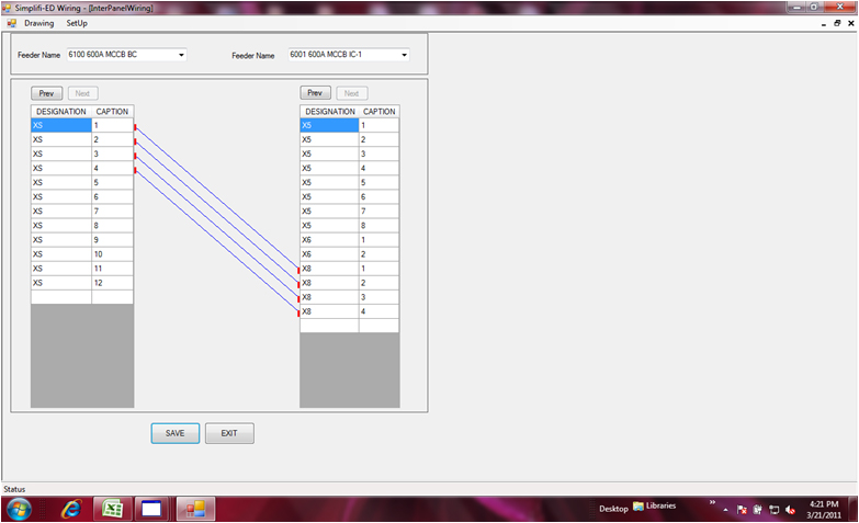
24. Inter-panel between multiple feeders can be created at Inter-panel interface screen by clicking the source and destination terminals of 2 different feeders.
25. Whenever the components are deleted at wiring, the same gets deleted/ removed automatically at all other pages like- BOQ/SLD/DOOR.
26. Revision marking and update at various reports are fully automated.
27. Auto marshalling or looping chart generation in wiring.
28. Generated drawings can be exported to CAD.
29. Marshalling drawings can be exported to EXCEL to do the additional modification if required.